
An Overview of O-RAN Architecture
After having looked at the O-RAN Alliance approach, philosophy, timelines, and architecture in brief, it is time to take a slightly more in-depth look at the O-RAN architecture. Before we delve further, be sure to revisit our RAN functional splits video which talks about the different CU/DU/RU splits and which layers go where. From the O-RAN point of view, split 7.2 is used for the fronthaul while split 2 may additionally be present, depending on the deployment scenario.
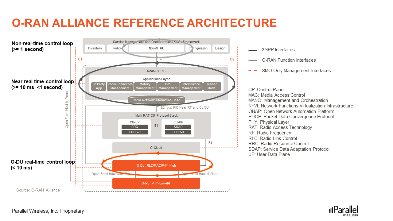
Figure 1: O-RAN Alliance Reference Architecture
While the O-RAN Philosophy blog post introduced the architecture the way it is currently depicted in the O-RAN specifications, their slightly older diagram works nicely when we need to explain the control loops.
The control loops are closed loop autonomous action and feedback loops designed for normal operation and/or optimization of the network by feeding it with real-time intelligence and analytics, thereby realizing the vision of autonomous and self-optimizing networks.
The first loop that should be highlighted is the Real-time O-DU Scheduler control loop, shown in orange in Figure 1 above. It is responsible for real-time processing of radio scheduling information, HARQ, beamforming, etc. The timing of the loop is less than 10 milliseconds, hence real-time.
The Near-real-time control loop operates between 10 milliseconds and 1 second and is associated with the Near-RT RIC. Finally, we have the non-real-time control loop which is associated with Non-RT RIC and operates at over 1 second.
It is important to highlight here that the execution timings for the real-time and non-real-time control loops are dependent on the use case. The O-DU scheduler loop on the other hand has to always operate below 10 milliseconds due to its real-time nature.
It should also be kept in mind that all of these loops run in parallel to each other and, depending on the use case, may or may not have any interaction between them. The use cases for the Non-RT RIC and Near-RT RIC control loops are fully defined by the O-RAN Alliance. For the O-DU scheduler control loop, only the relevant interactions with other O-RAN nodes or functions are defined as part of the O-RAN specifications.
Next, we will describe what is meant by O-Cloud, Near-RT RIC, Non-RT RIC, and SMO in a bit more detail.
O-Cloud
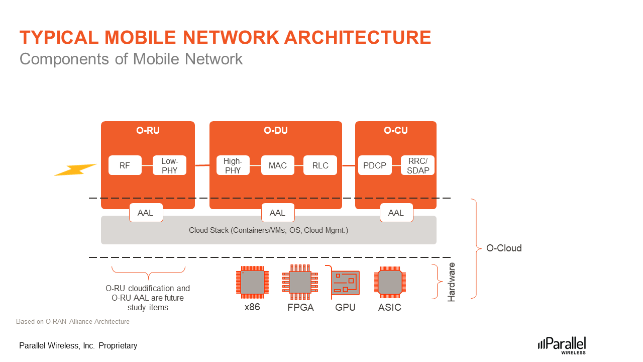
Figure 2: Components of O-RAN based mobile network architecture
The O-RAN Alliance defines O-Cloud as a cloud computing platform comprised of a collection of physical infrastructure nodes that meet O-RAN requirements to host the relevant O-RAN functions, the supporting software components, and the appropriate management and orchestration functions.
The term O-Cloud refers to a collection of O-Cloud resource pools at one or more location and the software to manage nodes and deployments hosted on them. An O-Cloud will include functionality to support both deployment-plane and management services.
When we talk about decoupling of hardware and software, or disaggregation or cloudification, the intention is that the software will reside on a COTS server on the cell site or in an Edge Cloud or in any data center located anywhere.
As you can see in Figure 2 above, there are 3 layers in play here:
- The top layer is virtualized RAN software functions.
- The middle layer includes Cloud Stack functions as well as Acceleration Abstraction Layer (AAL) functions.
- At the bottom is the hardware layer.
An O-Cloud Node is a collection of CPUs, memory, storage, NICs, BIOSes, BMCs, etc., and may include hardware accelerators to offload computational-intense functions with the aim of optimizing the performance of the O-RAN Cloudified Network Functions.
This is where the AAL Interface plays a role as it allows different software vendors’ network functions to work with different hardware and accelerators. The O-RAN specifications support a couple of different approaches that we won’t be detailing here.
The expectation is that someday in the future, even the O-RU will be cloudified and running on COTS servers. It would most likely need an AAL as well. The O-RAN specifications clarify that these are items which need further study in the future.
Near-RT RIC
As discussed in our earlier blog post, Near-RT RIC is a logical function that enables near-real-time control and optimization of RAN elements and resources via fine-grained data collection and actions over an E2 interface.
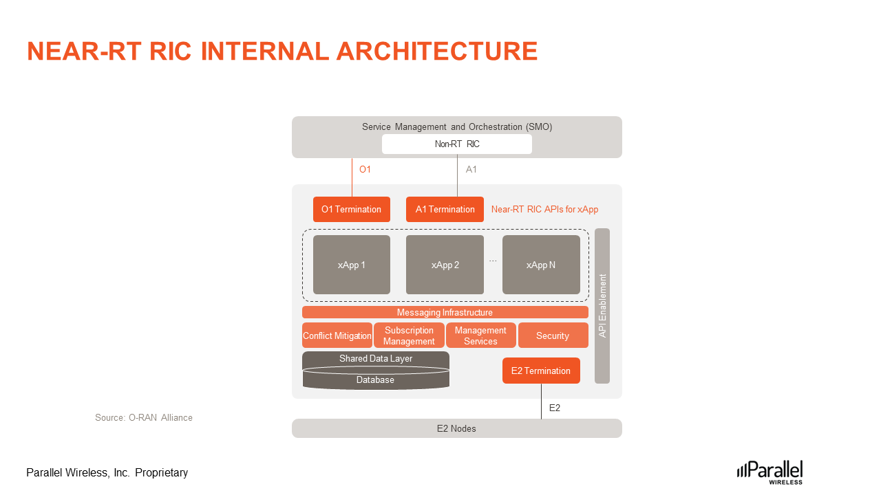
Figure 3: Near-RT RIC Internal Architecture
xApp, an application designed to run on the Near-RT RIC, is central to the operation of Near-RT RIC. A question that often comes up is, what does ‘x’ mean? ‘X’ stands for any, so any app designed to run on the Near-RT RIC.
Each xApp is likely to consist of one or more microservices. At the point of on-boarding, microservices will identify which data it consumes and which data it provides. The important point that has excited many within our industry is that these applications are independent of the Near-RT RIC and may be provided by any third party. The E2 interface enables a direct association between the xApp and the RAN functionality.
The companion video, embedded at the bottom of this blog post, details all of the blocks shown in Figure 3.
It is important to point out that sometimes there can be overlapping or conflicting requests from multiple xApps. This can lead to a tricky situation as each application will typically change one or more parameters with the objective of optimizing a specific metric. This is where Conflict Mitigation steps in to resolve any conflicting actions.
Service Management and Orchestration (SMO)
SMO is a Service Management and Orchestration system. In a Network, there can be many different management domains such as RAN management, Core management, Transport management, end-to-end slicing management etc. SMO is responsible for RAN domain management.
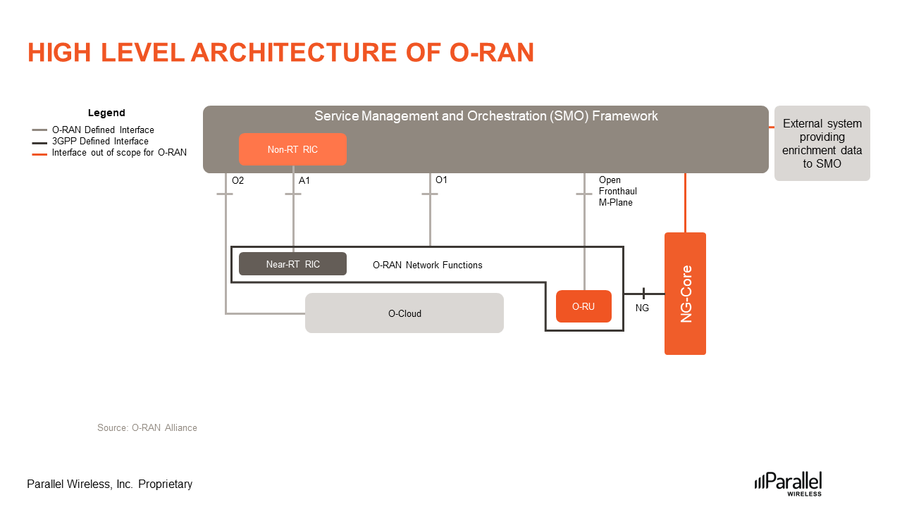
Figure 4: High-level architecture of O-RAN
SMO performs its services through four key O-RAN defined interfaces as can be seen in the high-level architecture diagram, Figure 4:
- The Open Fronthaul M-plane or Management plane interface between SMO and O-RU.
- A1 Interface between the Non-RT RIC in the SMO and the Near-RT RIC for RAN Optimization.
- O1 Interface between the SMO and the O-RAN Network Functions for FCAPS support. FCAPS is based on the ISO model which defines five conceptual areas for managing networks: fault, configuration, accounting, performance, and security.
- O2 Interface between the SMO and the O-Cloud to provide platform resources and workload management.
Non-RT RIC
The Non-RT RIC is defined as a logical function within SMO that drives the content carried across the A1 interface. The main reason it is portrayed as a function that resides within the SMO is that it is intended to communicate that the Non-RT RIC is comprised of a subset of functionality of the SMO itself.
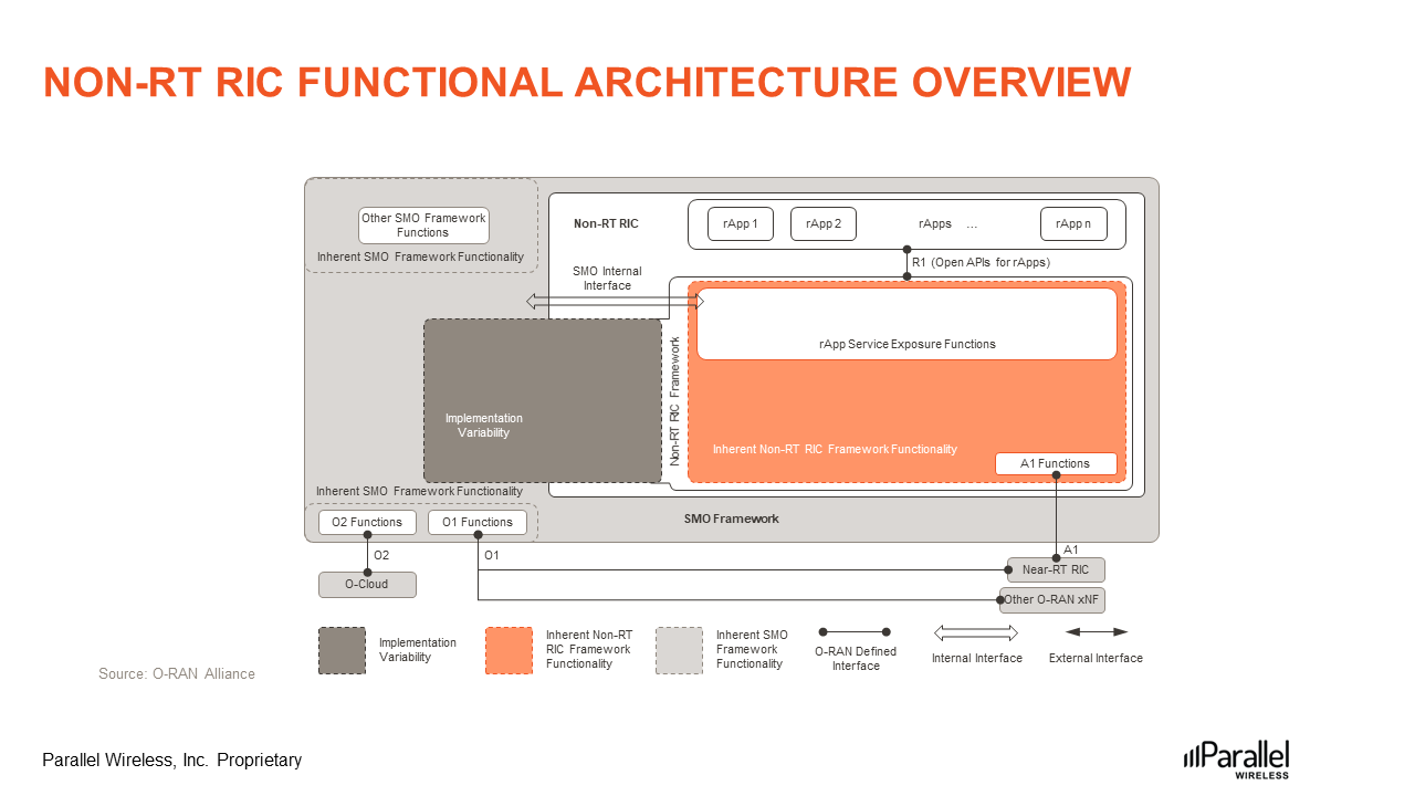
Figure 5: Non-RT RIC functional architecture overview
The Non-RT RIC enables non-real-time control and optimization of RAN elements and resources, it includes AI/ML workflow including model training and updates, and policy-based guidance of applications/features in the Near-RT RIC.
The reason for highlighting a direct association with the A1 interface is that it is intended to convey that the functionality of the Non-RT RIC is directly responsible for driving what is sent and received across the A1 interface.
In comparison, the O1 and O2 interfaces are shown as being directly associated with the SMO Framework itself, which is not specific to the Non-RT RIC. This representation again is intended to communicate that the SMO Framework functionality is directly responsible for driving what is carried across these interfaces.
In addition to the external A1 interface, there is also an internal R1 interface. The Non-RT RIC allows applications to run on it. These applications are called rApps, where ‘r’ stands for RAN. The Non-RT RIC exposes SMO Framework functions to “rApps” via a set of “rApp Services Exposure” functions over the R1 interface. As the R1 interface is the only interface between an rApp and the functionality of the Non-RT RIC and SMO, it should be defined to meet all functional needs of rApps, with appropriate interface extensibility capabilities as needed.
With respect to the Non-RT RIC, the companion video at the end details all of the different functional blocks within the Non-RT RIC.
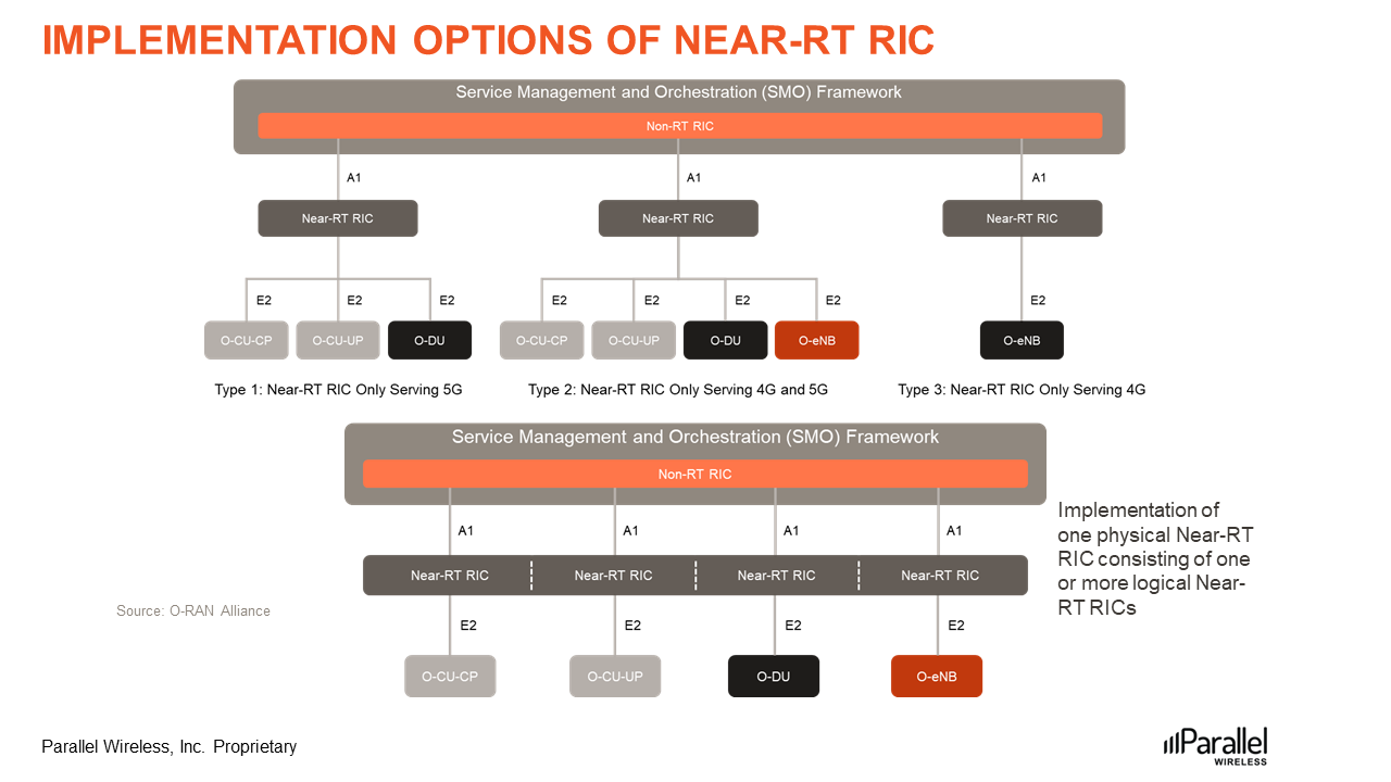
Figure 6: Implementation options of Near-RT RIC
Finally, it should be kept in mind that one Non-RT RIC can connect to multiple Near-RT RICs. It is also possible to have one physical Near-RT RIC consisting of one or more logical Near-RT RICs. Both of these implementation options are shown in Figure 6 above.
https://www.youtube.com/wath?v=B9fd4GdiLwI